Here I will be building the Madcow Torrent level 1 dual deployment high power model rocket. I have built smaller rockets in the past but this is my this is the first one that uses reloadable motors. I will be using a 4 grain 38mm motor that will hopefully propel the rocket to around 600m of altitude.
Unboxing:
After ordering the Madcow torrent and a couple of other accessories from Apogee Components, the Package arrived after 2 weeks (it was being shipped from the US to the UK). The contents were undamaged and well packed although the box had a small hole in it:


When I first looked over the parts, I thought I was missing the electronics bay but it was inside the top body tube. All the parts were undamaged and precisely laser cut although I would prefer if Madcow used a lighter and stronger material for the fins such as fiberglass rather than cheap, heavy plywood.
Engine mount:
The step in the build it to glue the centering plate onto the engine tube about 2-3cm from the end. This distance will vary depending on which engine retainer you are using. I was using the recommended retainer. PVA glue worked well for me although a stronger dedicated wood glue might be better.
 Make sure you leave a bit of space between the retainer and the centering ring so that you can add a fillet later. Next, do the same process for the top centering ring, leaving only 3mm or space for a fillet:
 Note: the image below is confusing, the top centering ring is actually on the bottom.Now, install the parachute cord anchor into the hole on the top ring:
 Don’t tighten the nut too hard or else the wood will get damaged. After doing so, put some superglue on the thread to prevent the nut from getting loose. Finally, securely tie one end of the shock cord to the loop.
Installing engine mount:
To install the engine mount into the body tube, I once again used the PVA glue. Initially, you only want to glue in the back centering ring by smearing glue on the interior of the body tube and pushing the engine mount In. Push the back centering ring about 2-3mm into the body tube in order to have space for a glue fillet.
 After the glue dries, it forms a strong fillet:
 Next, glue the forward centering ring by dripping the glue into the body tube and pushing it into the seam between the two parts using your fingers.
Installing fins:
As you may have noticed, this kit comes with pre-cut slots for the fins. This makes it easier to glue them in and the joint is much stronger. To glue them in, I smeared PVA glue all over protruding part of the fin and firmly pushed it in until I could feel that it was touching the motor tube. Installing all three as soon as possible will ensure that the motor tube is in the center because the fins will exert even pressure on it from all sides.  Once the glue has dried, it is time to make the fin fillets. I used a cheap two part “bonding putty” called Fix-IT that I found on eBay.
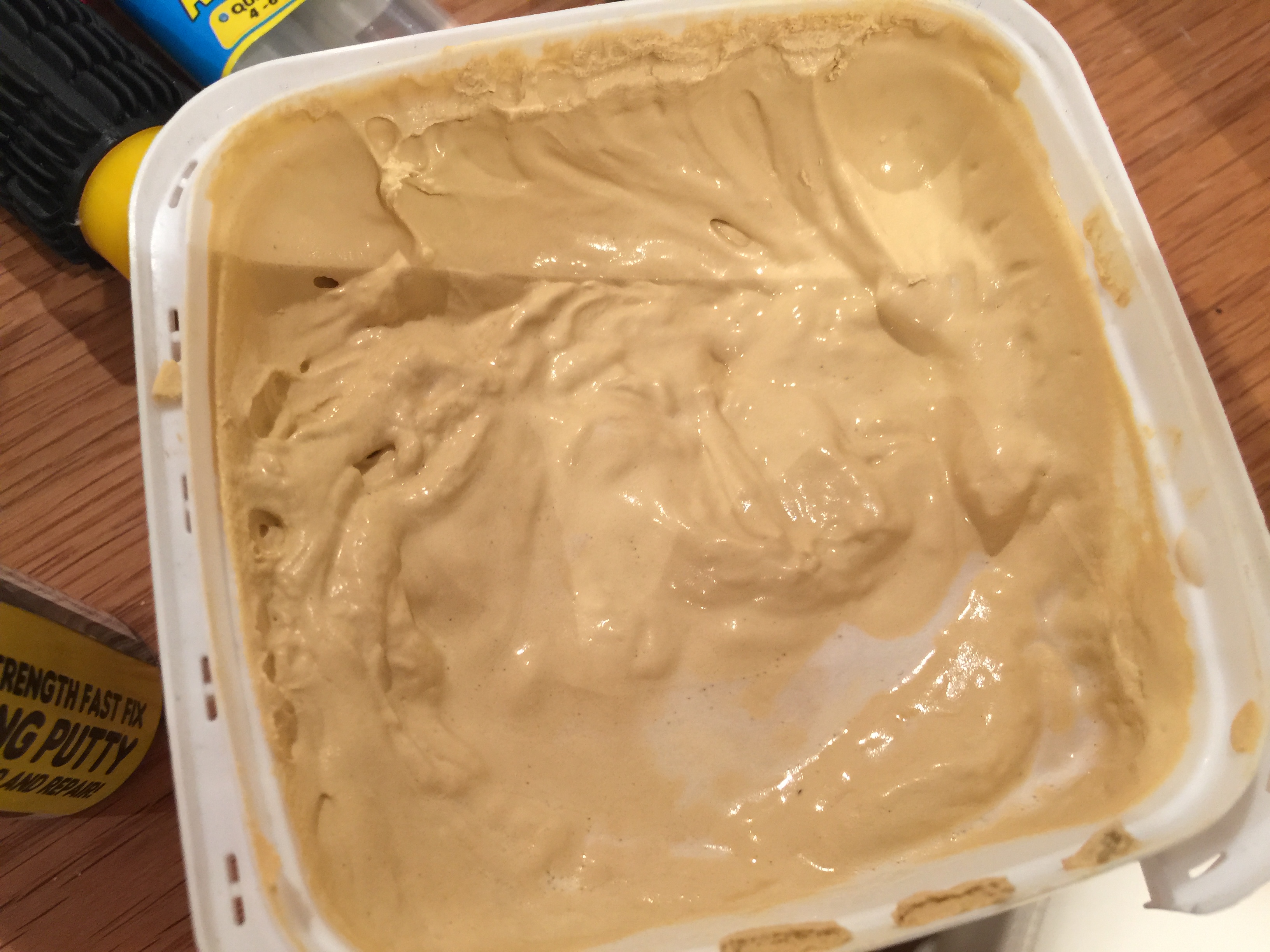
  As you can see on the image below, the ratio of the two clays is already pre-determined so all you have to do is cut of a bit of the cylinder and mix the two together. Make sure you wear gloves while mixing because it is very difficult clean your hands after handling the putty.
 Once the putty is mixed, it will instantly start to harden so only do one fillet at a time. Knead the clay into a long roll and firmly push it between the fin and the body tube. Try to get the surface of the fillet as smooth and uniform as possible.
Once the putty has fully cured, sand it until the surface is smooth. If it remains uneven, use some wood filler and apply it over the putty:
 Once the filler has dried, sand it and the fillet should now be done.
Motor retainer:
 Once the fin fillets have been completed, I glued the motor retainer to the motor mount using a two part epoxy
Electronics bay:
The first step in building the electronics bay was to assemble the housing in which the sled will go. The housing consists of two parts, the main tube that will go inside the rocket’s body tube and a centering ring to hold the tube in place. This electronics bay also acts as a coupler between the top and bottom of the rocket. After building the housing, I glued together the sled and fastened it to the threaded rods
 I then installed my altimeter/parachute deployment controller, the arming switch and the battery. I used a easymini from altus metrum as a parachute deployment controller.
 To attach the easymini to the sled securely, I epoxied four screws to the base and attached the easymini onto them.
to finish the electronics bay, I assembled the top and bottom closures
Launch lugs:
to secure the launch lugs to the body tube, the rear one is screwed into the motor’s wooden centering ring and the front one screws into a part that is installed on the other side of the body tube wall.

 The rocket is now completed and ready for painting. Here is a video that describes how I painted this rocket:
Launching the rocket
Recently I had the opportunity to visit the monthly launch event at the East Anglican Rocketry Society (EARS) where I launched this rocket. I used a 2 grain 38mm reloadable motor from ceasaroni with the delay set to 9 seconds and a 36 inch parachute. Unfortunately, the engine mount bulkhead onto which the eye bolt is attached was too thin and during parachute deployment it got ripped apart resulted in the lower part of the rocket falling without a parachute. Due to this fall, two of the fins became loose but fortunately, fixing the bulkhead and the fins only needed a large amount of epoxy and was easy to complete.

No Comments Yet